---
title: Mount a LTE Cat M1 or Cat 1 BIS Gateway on a commercial refrigeration cabinet
description: A guide for locating an AoFrio Gateway on a commercial refrigeration cabinet, normally used for cold beverages.
---
[Skip to content](https://support.aofrio.com/mount-a-gateway-on-a-commercial-refrigeration-cabinet#main-content)
- [English](https://support.aofrio.com/mount-a-gateway-on-a-commercial-refrigeration-cabinet)
- [Español - México](https://support.aofrio.com/es-mx/mount-a-gateway-on-a-commercial-refrigeration-cabinet)
- [Português - Brasil](https://support.aofrio.com/pt-br/mount-a-gateway-on-a-commercial-refrigeration-cabinet)
English
Show submenu for translations

Open main navigation
Close main navigation
- - [English](https://support.aofrio.com/mount-a-gateway-on-a-commercial-refrigeration-cabinet)
- [Español - México](https://support.aofrio.com/es-mx/mount-a-gateway-on-a-commercial-refrigeration-cabinet)
- [Português - Brasil](https://support.aofrio.com/pt-br/mount-a-gateway-on-a-commercial-refrigeration-cabinet)
English
Show submenu for translations
- Contact us
Contact us
How can we help you?
- There are no suggestions because the search field is empty.
1. [Help Center](https://support.aofrio.com/?hsLang=en)
2. [Mounting & commissioning hardware](https://support.aofrio.com/mounting-commissioning-hardware?hsLang=en)
3. [Gateway](https://support.aofrio.com/mounting-commissioning-hardware?hsLang=en#gateway)
June 8, 2026
# Mount a LTE Cat M1 or Cat 1 BIS Gateway on a commercial refrigeration cabinet
## A guide for locating an AoFrio LTE Cat M1 or Cat 1 BIS Gateway on a commercial refrigeration cabinet, normally used for cold beverages.
- [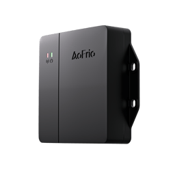Step 1 - Plan where to mount the Gateway](https://support.aofrio.com/mount-a-gateway-on-a-commercial-refrigeration-cabinet#step1)
- [Step 2 - Attach the Gateway to the cooler](https://support.aofrio.com/mount-a-gateway-on-a-commercial-refrigeration-cabinet#step2)
- [Step 3 - Connect to the power supply](https://support.aofrio.com/mount-a-gateway-on-a-commercial-refrigeration-cabinet#step3)
- [Step 4 - (Optional) Further secure the position of the device and cables](https://support.aofrio.com/mount-a-gateway-on-a-commercial-refrigeration-cabinet#step4)
- [Step 5 - Use the LEDs to confirm operation](https://support.aofrio.com/mount-a-gateway-on-a-commercial-refrigeration-cabinet#step5)
- [Step 6 - Pairing with an SCS Controller or temperature sensor](https://support.aofrio.com/mount-a-gateway-on-a-commercial-refrigeration-cabinet#step6)
---
### Step 1 - Plan where to mount the Gateway
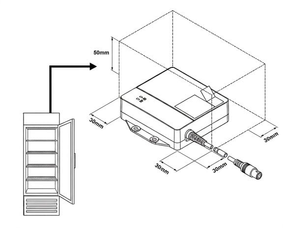
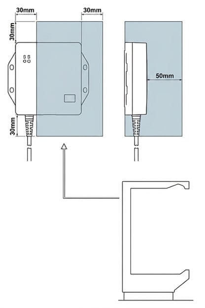
- While the mounting location can vary widely depending on the asset type (e.g., Open Deck cooler, Bottle cooler, Ice cream chest freezer), we recommend that you mount the Gateway:
- **At or near the top of the cooler** for the best cellular performance when possible. This is especially relevant when paired with an SCS Controller that may be mounted closer to the equipment’s motor or compressor.
- **Behind plastic paneling or a grid** as these are less likely to interfere with communications - as metal paneling can. (see diagrams below)
- **Out of sight from customers** to minimize the risk of theft or tampering.
- If you are mounting the Gateway in a location that isn’t easily accessible for later QR code scanning, of its QR code, you can attach a duplicate QR code sticker on a more accessible location on the outside of the cooler.
- Consider how you will wire the Gateway to AC mains supply within the cooler to power the device.
---
### Step 2 - Attach the Gateway to the cooler
Choose between:
- **Screw mounting** - Use 2 to 4, 8G (4.2mm) screws if screw mount is required. Screw type will depend on material. For example, use a stainless steel 8G 19mm self-drillingf drilling screw when installing Gateway to a metal plate and set drive torque appropriate to material type and thickness to avoid damaging screw thread or Gateway enclosure. Maximum allowed torque to prevent damage to the enclosure is 3Nm.
1. Mark and drill pilot holes.
2. Use a screwdriver to secure the device to the cabinet surface.
- **Tape mounting**
1. Ensure the mounting surface and the back of the device are clean and dry.
2. Stick the adhesive pad to the back of the device.
3. Firmly press the device into position, ensuring it is secured to the surface.
---
### Step 3 - Connect to the power supply
- Connect the AC wires to the AC distribution point using AC terminations as per local regulations.
- Wire the AC side of the power supply to the cooler mains using your preferred connectors. 100-240V AC, 50/60Hz.
- The AC cable is supplied with open ends. We recommend that you terminate the AC cable with an appropriate connector to allow easy integration with the cabinet AC wiring.
NOTE: The Gateway is powered by mains power through an interconnecting cable that requires a protective 3A circuit breaker.
---
### Step 4 - (Optional) Further secure the position of the device and cables
- Use cable ties to avoid unplugging the Gateway when the cooler is moved.
---
### Step 5 - Use the LEDs to confirm operation
- Green LED = external power status
- On – not flashing = Power is connected
- On – flashing every second = Running from battery
- Off (Flight mode)
- Red LED = Cellular network connectivity status
- Slow short flash - searching for cellular network
- Slow long flash - connected to a cellular network, idle
- Fast flash - connected to a cellular network, sending data
---
### Step 6 - Pairing with an SCS Controller or temperature sensor
Timing for this step depends on your setup plan - eg if you are pairing in the factory or at the location where the cooler will be operating.
**Install address?** The install address for a Gateway comes from the SCS Controller or Monitor it is paired with. To ensure the correct address appears in AoFrio software, add the install address when commissioning the SCS Controller or Monitor using Field app.
Read more:
- [Pairing a Gateway with an SCS Controller](https://support.aofrio.com/pair-the-scs-controller-with-a-gateway?hsLang=en)
- [Pairing a Gateway with a Monitor](https://support.aofrio.com/pair-the-monitor-with-a-gateway?hsLang=en)
---
### Troubleshooting
If the Gateway fails to operate, please check the following:
- Ensure that the Gateway is connected to the AC power outlet.
- Ensure that the voltage and current requirements of the device are within the specifications of the power
- [Support for your role](https://support.aofrio.com/support-for-your-role?hsLang=en#main-content)
- [Service technician](https://support.aofrio.com/support-for-your-role?hsLang=en#service-technician)
- [Hardware installer](https://support.aofrio.com/support-for-your-role?hsLang=en#hardware-installer)
- [OEM buyer or engineer](https://support.aofrio.com/support-for-your-role?hsLang=en#oem-buyer-or-engineer)
- [Fleet manager](https://support.aofrio.com/support-for-your-role?hsLang=en#fleet-manager)
- [Food Safety manager](https://support.aofrio.com/support-for-your-role?hsLang=en#food-safety-manager)
- [Your AoFrio account](https://support.aofrio.com/support-for-your-role?hsLang=en#your-aofrio-account)
- [Frequently Asked Questions (FAQ)](https://support.aofrio.com/support-for-your-role?hsLang=en#frequently-asked-questions-faq)
- [Identify & recover lost assets](https://support.aofrio.com/identify-recover-lost-assets?hsLang=en#main-content)
- [Asset protection](https://support.aofrio.com/identify-recover-lost-assets?hsLang=en#asset-protection)
- [Asset identification & tracking](https://support.aofrio.com/identify-recover-lost-assets?hsLang=en#asset-identification-tracking)
- [Software & Firmware releases](https://support.aofrio.com/software-firmware-releases?hsLang=en#main-content)
- [Release notifications](https://support.aofrio.com/software-firmware-releases?hsLang=en#release-notifications)
- [Firmware for IoT hardware](https://support.aofrio.com/software-firmware-releases?hsLang=en#firmware-for-iot-hardware)
- [About our software & platform](https://support.aofrio.com/about-our-software-platform?hsLang=en#main-content)
- [General](https://support.aofrio.com/about-our-software-platform?hsLang=en#general)
- [iQ platform](https://support.aofrio.com/about-our-software-platform?hsLang=en#iq-platform)
- [Field app](https://support.aofrio.com/about-our-software-platform?hsLang=en#field-app)
- [Track app](https://support.aofrio.com/about-our-software-platform?hsLang=en#track-app)
- [Food Retail](https://support.aofrio.com/about-our-software-platform?hsLang=en#food-retail)
- [User Manager](https://support.aofrio.com/about-our-software-platform?hsLang=en#user-manager)
- [Report app](https://support.aofrio.com/about-our-software-platform?hsLang=en#report-app)
- [Lab app](https://support.aofrio.com/about-our-software-platform?hsLang=en#lab-app)
- [OEM Dashboard](https://support.aofrio.com/about-our-software-platform?hsLang=en#oem-dashboard)
- [Cradle app](https://support.aofrio.com/about-our-software-platform?hsLang=en#cradle-app)
- [Universal Programmer app](https://support.aofrio.com/about-our-software-platform?hsLang=en#universal-programmer-app)
- [IoT hardware](https://support.aofrio.com/iot-hardware?hsLang=en#main-content)
- [IoT ecosystem](https://support.aofrio.com/iot-hardware?hsLang=en#iot-ecosystem)
- [Gateway - LTE Cat M1 & LTE Cat 1 BIS](https://support.aofrio.com/iot-hardware?hsLang=en#gateway-lte-cat-m1-lte-cat-1-bis)
- [SCS Controller - General information](https://support.aofrio.com/iot-hardware?hsLang=en#scs-controller-general-information)
- [SCS 800 Controller](https://support.aofrio.com/iot-hardware?hsLang=en#scs-800-controller)
- [SCS 500 & 600 Controller](https://support.aofrio.com/iot-hardware?hsLang=en#scs-500-600-controller)
- [Monitor](https://support.aofrio.com/iot-hardware?hsLang=en#monitor)
- [Network Pro](https://support.aofrio.com/iot-hardware?hsLang=en#network-pro)
- [Compact LoRaWAN Temperature Sensor](https://support.aofrio.com/iot-hardware?hsLang=en#compact-lorawan-temperature-sensor)
- [LoRaWAN Gateway](https://support.aofrio.com/iot-hardware?hsLang=en#lorawan-gateway)
- [Mounting & commissioning hardware](https://support.aofrio.com/mounting-commissioning-hardware?hsLang=en#main-content)
- [General](https://support.aofrio.com/mounting-commissioning-hardware?hsLang=en#general)
- [Gateway](https://support.aofrio.com/mounting-commissioning-hardware?hsLang=en#gateway)
- [SCS Controller](https://support.aofrio.com/mounting-commissioning-hardware?hsLang=en#scs-controller)
- [Motors & fans](https://support.aofrio.com/mounting-commissioning-hardware?hsLang=en#motors-fans)
- [Temperature sensors](https://support.aofrio.com/mounting-commissioning-hardware?hsLang=en#temperature-sensors)
- [Network Pro](https://support.aofrio.com/mounting-commissioning-hardware?hsLang=en#network-pro)
- [IoT hardware operation & behavior](https://support.aofrio.com/iot-hardware-operation-behavior?hsLang=en#main-content)
- [Cellular & Bluetooth connectivity](https://support.aofrio.com/iot-hardware-operation-behavior?hsLang=en#cellular-bluetooth-connectivity)
- [Optimize cooler performance & energy use](https://support.aofrio.com/iot-hardware-operation-behavior?hsLang=en#optimize-cooler-performance-energy-use)
- [SCS Controller](https://support.aofrio.com/iot-hardware-operation-behavior?hsLang=en#scs-controller)
- [SCS Controller - Parameters](https://support.aofrio.com/iot-hardware-operation-behavior?hsLang=en#scs-controller-parameters)
- [SCS Controller - Faults & Alarms](https://support.aofrio.com/iot-hardware-operation-behavior?hsLang=en#scs-controller-faults-alarms)
- [Monitor](https://support.aofrio.com/iot-hardware-operation-behavior?hsLang=en#monitor)
- [Gateway](https://support.aofrio.com/iot-hardware-operation-behavior?hsLang=en#gateway)
- [Network Pro](https://support.aofrio.com/iot-hardware-operation-behavior?hsLang=en#network-pro)
- [Motors & fans](https://support.aofrio.com/motors-fans?hsLang=en#main-content)
- [General](https://support.aofrio.com/motors-fans?hsLang=en#general)
- [ECR 2 26W motor](https://support.aofrio.com/motors-fans?hsLang=en#ecr-2-26w-motor)
- [ECR 2 13W motor](https://support.aofrio.com/motors-fans?hsLang=en#ecr-2-13w-motor)
- [ECR 1 motor](https://support.aofrio.com/motors-fans?hsLang=en#ecr-1-motor)
- [ECR 82/92 motor](https://support.aofrio.com/motors-fans?hsLang=en#ecr-82-92-motor)
- [Fan packs - 13W applications](https://support.aofrio.com/motors-fans?hsLang=en#fan-packs-13w-applications)
- [Fan packs - 26W applications](https://support.aofrio.com/motors-fans?hsLang=en#fan-packs-26w-applications)
- [Other fans](https://support.aofrio.com/motors-fans?hsLang=en#other-fans)
- [Manuals & datasheets](https://support.aofrio.com/manuals-datasheets?hsLang=en#main-content)
- [IoT hardware](https://support.aofrio.com/manuals-datasheets?hsLang=en#iot-hardware)
- [Motors and fans](https://support.aofrio.com/manuals-datasheets?hsLang=en#motors-and-fans)
- [Software](https://support.aofrio.com/manuals-datasheets?hsLang=en#software)
- [Special access resources](https://support.aofrio.com/special-access-resources?hsLang=en#main-content)
- [General](https://support.aofrio.com/special-access-resources?hsLang=en#general)
[](https://aofrio.com/)
78 Apollo Drive, Rosedale, Auckland 0632
New Zealand
Copyright © 2025, AoFrio Limited